-
Products
-
Industries
Industries
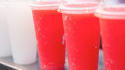
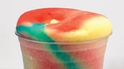
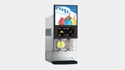
Quickly increase your profits by meeting the growing demand for frozen beverages.
-
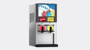
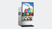
All Dispensers
All Dispensers
We offer low maintenance, reliable and innovative custom-built equipment.
-
Resource Center
Resource Center
Get technical support, download training materials, and learn more about the frozen beverage industry.
Support & Services Resources